Not Logic Gate Circuit Diagram
Logic circuits and switching theory Logic circuit gcse gates circuits computerscience Pin on circuits
CMOS Logic Circuit Design for AND and OR Gate - YouTube
How to create a logic gate diagram Digital logic Cmos logic circuit design for and and or gate
Circuits logic gates simplify output diagram example boolean questions
Logic gates nand gate transistors circuits transistor make circuit basic two buffers simply microchip verilog starting diy electrical stack sourceLogic combinational circuits constructing Logic gates truth boolean circuits chart construct nand logique nutsvolts formulas mathematics inputs porteComputing:) : chapter 3- logic circuits.
Combinational circuits logic gates electronics circuit boolean algebra operators engineering combination logical schematic nand define kombinasi electronic values arithmetic switchesLogic circuits gates computing types electronic hardware Digital electronicsLogic circuits gate circuit sparkfun logika gerbang pinout dip input counter timer dihubungkan sebuah connected.

Gates logic series using two digital schematic why circuit diagram odd circuitlab created
Laptop diagram: schematic diagram using combinational logic gateOr gate schematic diagram / logic diagram software / to add an instance Logic gate: types including circuit diagram, symbols and usesGate logic tables inverter gif gates truth electronics basic digital.
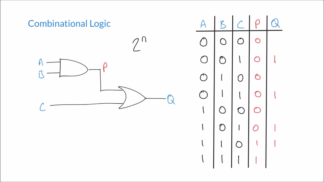
Lesson : combinational logic circuit example 1 – hyperelectronicCmos gate logic circuit Logic gatesGate logic symbol shape computing mcgill truth keys parallel.

Logic gates truth table generator
Understanding digital buffer, gate, and logic ic circuitsLogic circuit combinational The following logic gate circuit is equivalent to:\n \n \n \n \n (aLogic gates and logic circuits.
Or gate schematic diagram / logic gates and gate or gate truth tableLogic adder example2 alarm Gate logic diagram circuit nand types uses principle workingCorresponds neet.

The circuit diagram shown here corresponds to the logic gate,
Logic gate circuits two switching theory figureLogic equivalent nand jee xor 11+ logic gates circuit diagramGate ic buffer digital circuits logic gates symbols basic understanding part nutsvolts truth nand negative input tables positive figure nuts.
Transistor logic gerbang npn inverter ttl rtl gatter nor logika resistors input dasar aufgebaut command inverted diagramsIntegrated circuits Computing:) : chapter 3- logic circuitsLogic gate schematic logical input.

Computing:) : Chapter 3- Logic Circuits

Integrated Circuits | innovative element maker space

digital logic - Why have two NOT gates in series? - Electrical

Understanding Digital Buffer, Gate, and Logic IC Circuits - Part 1

The following logic gate circuit is equivalent to:\n \n \n \n \n (A
Logic Gates Truth Table Generator | Review Home Decor

CMOS Logic Circuit Design for AND and OR Gate - YouTube

Logic Circuits and switching Theory